Product Description
With 30-year rich industry experience and knowledge, we have earned specialization in manufacturing and supplying superior quality Large Gears. These are fabricated in conformity with defined industry standards, these compact and sturdy gears have standard working speed and torque measurement. The offered range is widely acknowledged by the customers for features like optimum performance, robust construction and longer life. These precision engineered gears are widely demanded across varied industries, where large gear reduction is required.
Advantages:
– Products with Customers’ Designs
– Strong Machining & Heat Treatment Abilities
– Strict Quality Control
– Prompt Delivery
-Experience in Cooperation with Fortune 500 Companies
Process:
Forging/Casting
Normalizing&Tempering-Proof Machinnig
Quenching&Tempering
Finish Machining(Teeth Grinding)
We can offer you in various process conditions
Solutions for Many End Markets and Applications
–Mining
–Metallurgy
–Power Generation
–Sugar
–Cement Plant
–Port Machinery
–Oil and natural
–Papermaking
–OEM gear case
–General Industrial
Specifications of Gear :
| No. | Item | Description |
| 1 | Diameter | ≤15m |
| 2 | Module | ≤45 |
| 3 | Material | Cast Alloy Steel, Cast Carbon Steel, Forged Alloy Steel, Forged Carbon Steel |
| 4 | Structure From | Integrated, Half to Half, Four Pieces and More Pieces |
| 5 | Heat Treatment | Quenching & Tempering, Normalizing & Tempering, Carburizing & Quenching & Tempering |
| 6 | Tooth Form | Annular Gear, Outer Gear Ring |
| 7 | Standard | ISO, EN, DIN, AISI, ASTM, JIS, IS, GB |
Inspection and Test Outline of Girth Gear:
| No. | Item | Inspection Area | Acceptance Criteria | Inspection Stage | Certificates |
| 1 | Chemical Composition | Sample | Material Requirement | When Smelting After Heat Treatment |
Chemical Composition Report |
| 2 | Mechanical Properties | Sample(Test Bar on the Gear Body) | Technical Requirement | After Heat Treatment | Mechanical Properties Report |
| 3 | Heat Treatment | Whole Body | Manufacturing Standard | During Heat Treatment | Heat Treatment Report Curves of Heat Treatment |
| 4 | Hardness Test | Tooth Surface, 3 Points Per 90° | Technical Requirement | After Heat Treatment | Hardness Teat Report |
| After Semi Finish Machining | |||||
| 5 | Dimension Inspection | Whole Body | Drawing | After Semi Finish Machining | Dimension Inspection Report |
| Finish Machining | |||||
| 6 | Magnetic Power Test (MT) | Tooth Surface | Agreed Standard | After Finish Gear Hobbing | MT Report |
| 7 | UT | Spokes Parts | Agreed Standard | After Rough Machining | UT Report |
| After Welded | |||||
| After Semi Finish Machining | |||||
| 8 | PT | Defect Area | No Defect Indicated | After Digging After Welded |
PT Record |
| 9 | Mark Inspection | Whole Body | Manufacturing Standard | Final Inspection | Pictures |
| 10 | Appearance Inspection | Whole Body | CIC’s Requirement | Before Packing (Final Inspection) |
|
| 11 | Anti-rust Inspection | Whole Body | Agreed Anti-rust Agent | Before Packing | Pictures |
| 12 | Packing Inspection | Whole Body | Agreed Packing Form | During Packing | Pictures |
Facilities For Manufacturing Gear ring:
| No. | Item | Description |
| 1 | Smelting & Casting Capability | 40t ,50t, 80t Series AC Electric Arc Furnace 2×150t, 60t LF Ladle Refining Furnace 150t, 60t Series VD/VOD Furnace 20×18m Large Pouring Facility We can pour 900t refining liquid steel one time, and achieve vacuum poured 600t steel ingots. We can produce the high quality steel of more than 260 steel grades as carbon steel,structural alloy steel and the structural steel, refractory steel and stainless steel of special requirement. The maximum weight of casting steel, gray casting, graphite cast iron and non-ferrous casting is 600t, 200t, 150t and 20t separately. |
| 2 | Forging Capability | The only one in the word, the most technologically advanced and the largest specification18500t Oil Press, equipped with 750t.m forging operation machine 8400t Water Press 3150t Water Press 600t Water Press Φ5m High Precision Ring Mill ( WAGNER,Germany) Φ12m High Precision Ring Mill We can roll rings of different sections of carbon steel, alloy steel, high temperature alloy steel and non-ferrous alloys such as copper alloy, aluminum alloy and titanium alloy. Max. Diameter of rolled ring will be 12m. |
| 3 | Heat Treatment Capability | 9×9×15m,8×8×12m,6×6×15m,15×16×6.5m,16×20×6m ,7×7×17m Series Heat Furnace and Heat Treatment Furnaces φ2.0×30m,φ3.0×5.0m Series Heat Treatment Furnaces φ5.0×2.5m,φ3.2×1.5m,φ3.0×5.0m,φ2.0×5m Series Carburizing Furnaces & Nitriding Furnaces & Quenching Bathes φ2.0×30m Well Type CNC Electrical Furnaces Φ3.0×5.0M Horizontal Gas Temperature-differential Furnace Double-frequency and Double-position Quenching Lathe of Pinion Shaft |
| 4 | Machining Capability | 1. ≥5m CNC Heavy Duty Vertical Lathes 12m CNC Double-column Vertical Lathe 10m CNC Double-column Vertical Lathe 10m CNC Single-column Vertical Lathe 6.3m Heavy Duty Vertical Lathe 5m CNC Heavy Duty Vertical Lathe |
| 2. ≥5m Vertical Gear Hobbing Machines 15m CNC Vertical Gear Hobbing Machine 10m Gear Hobbing Machine 8m Gear Hobbing Machine 5m Gear Hobbing Machine 3m Gear Hobbing Machining |
||
| 3. Imported High-precision Gear Grinding Machines 0.8m~3.5m CNC Molding Gear Grinding Machines |
||
| 4. Large Boring & Milling Machines 220 CNC Floor-mounted Boring & Milling Machine 200 CNC Floor-mounted Boring & Milling Machine 160 CNC Floor-mounted Boring & Milling Machine |
Testing Process:
· QA DOC: Chemical Composition Report, Mechanical Properties Report, UT Report, Heat Treatment Report, Dimensions Check Report
· The data on chemical composition report and mechanical properties report are approved by third party, HangZhou Ship Material Research Institute, CSIC.
· UT test: 100% ultrasonic test according to EN15718-3, SA388, Sep 1921 C/c etc.
· Heat Treatment Report: provide original copy of heat treatment curve/time table.
Girth Gear Packing Picture
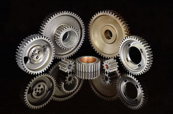
Main Facilites for Gear Manufacturing
Other Related Spare Parts
| Application: | Industry |
|---|---|
| Hardness: | According to Customers′ Requirementa |
| Manufacturing Method: | Cast Gesr, Forged Gear |
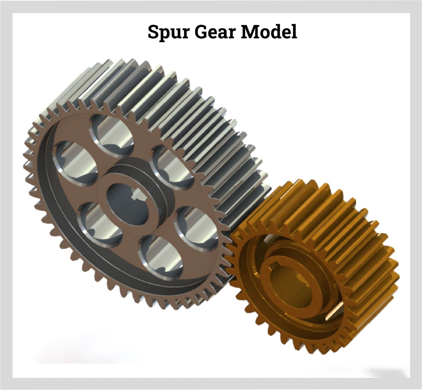
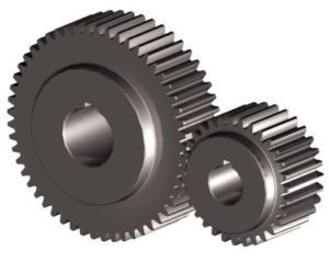
| Toothed Portion Shape: | Spur Gear |
| Material: | Cast Steel, Forged Steel |
| Type: | Circular Gear |
| Customization: |
Available
| Customized Request |
|---|
Can spur gears be used in both horizontal and vertical orientations?
Yes, spur gears can be used in both horizontal and vertical orientations. Here’s a detailed explanation:
Spur gears are one of the most common types of gears used in various applications. They have straight teeth that are parallel to the gear axis and are designed to transmit power and torque between parallel shafts. The versatility of spur gears allows them to be used in different orientations, including horizontal and vertical configurations.
Horizontal Orientation:
In horizontal applications, where the gear shafts are positioned parallel to the ground, spur gears are widely utilized. Horizontal orientations are commonly found in machinery such as conveyor systems, automobiles, industrial equipment, and many other applications. Spur gears in horizontal configurations can efficiently transmit power and torque between shafts, providing reliable operation and smooth gear engagement.
Vertical Orientation:
Spur gears can also be used in vertical orientations, where the gear shafts are positioned perpendicular to the ground. Vertical gear arrangements are often encountered in applications such as wind turbines, elevators, vertical conveyor systems, and various industrial machinery. In these cases, the weight of the gears and any additional loads acting on them must be considered to ensure proper load distribution and support. Adequate lubrication and proper gear design, including tooth profile and material selection, are important factors to ensure reliable and efficient operation in vertical orientations.
When using spur gears in vertical orientations, some additional considerations may be necessary due to the effects of gravity and potential oil leakage. In vertical applications, gravity can affect the distribution of lubricant, potentially leading to inadequate lubrication of gear teeth. Proper lubrication techniques and lubricant selection should be employed to ensure sufficient film thickness and minimize wear. Additionally, seals or other measures may be required to prevent oil leakage, especially in applications where high-speed rotation or high loads are involved.
It’s important to note that while spur gears can be used in both horizontal and vertical orientations, the specific design and configuration of the gear system should be evaluated to ensure optimal performance and longevity. Factors such as load distribution, gear alignment, lubrication, and material selection should be carefully considered based on the intended orientation and operating conditions of the gear system.
Consulting with gear manufacturers, engineers, or industry experts can provide further guidance on the suitability and design considerations when using spur gears in horizontal or vertical orientations.
Can you provide examples of machinery that use spur gears?
Spur gears are widely used in various machinery and mechanical systems due to their simplicity, efficiency, and versatility. Here are some examples of machinery and equipment that commonly utilize spur gears:
- Automotive Industry: Spur gears are found in various automotive applications, including manual transmissions, differential gears, and starter motors. They are used to transmit power and torque efficiently in these systems.
- Mechanical Clocks and Watches: Traditional mechanical clocks and watches often utilize spur gears to transfer rotational motion from the mainspring to the hour, minute, and second hands. These gears play a crucial role in accurate timekeeping.
- Printing Presses: Spur gears are employed in printing presses to synchronize the movement of different components, such as rollers and paper feed mechanisms. They ensure precise and coordinated operation during the printing process.
- Industrial Machinery: Many types of industrial machinery rely on spur gears, including conveyors, packaging equipment, textile machinery, and machine tools. Spur gears help transmit power and control the movement of various components in these machines.
- Power Plants: Spur gears can be found in power generation facilities, such as steam turbines and gas turbines. They help transfer rotational motion from the turbine shaft to the generator shaft, enabling the production of electrical power.
- Agricultural Equipment: Agricultural machinery, such as tractors, combines, and harvesters, often utilize spur gears in their drive systems. These gears help transmit power from the engine to the wheels or other operational components.
- Robotics and Automation Systems: Spur gears are commonly used in robotics and automation systems to transmit power and control the movement of robotic arms, conveyor systems, and other mechanical components.
- Power Tools: Many power tools, including drills, saws, and grinders, incorporate spur gears in their gearboxes. These gears help increase torque and provide the necessary speed reduction for efficient tool operation.
These examples represent just a few of the many applications where spur gears are utilized. Spur gears’ simplicity, cost-effectiveness, and ability to handle high load capacities make them suitable for a wide range of machinery and mechanical systems in various industries.
It’s important to note that different gear types, such as helical gears, bevel gears, or planetary gears, may also be used in conjunction with spur gears or in different applications depending on specific requirements and design considerations.
What is a spur gear and how does it work?
A spur gear is a type of cylindrical gear with straight teeth that are parallel to the gear axis. It is one of the most common and simplest types of gears used in various mechanical systems. Spur gears work by meshing together to transmit rotational motion and torque between two parallel shafts. Here’s a detailed explanation of spur gears and how they work:
A spur gear consists of two or more gears with cylindrical shapes and an equal number of teeth. These gears are mounted on parallel shafts, and their teeth mesh together to transfer rotational motion from one gear to another. The gear with power input is called the “drive gear” or “driver,” while the gear receiving the power output is called the “driven gear” or “follower.”
The key characteristics and components of spur gears include:
- Teeth: Spur gears have straight teeth that are cut parallel to the shaft axis. The teeth are evenly spaced around the circumference of the gear. The number of teeth determines the gear ratio and affects the speed and torque transmission between the gears.
- Pitch Diameter: The pitch diameter is the theoretical diameter of the gear at the point where the teeth mesh. It is determined by the number of teeth and the module or diametral pitch of the gear.
- Module or Diametral Pitch: The module is a parameter used in metric gear systems, while the diametral pitch is used in imperial gear systems. They define the tooth size and spacing of the gear. The module is the ratio of the pitch diameter to the number of teeth, while the diametral pitch is the number of teeth per inch of pitch diameter.
- Pressure Angle: The pressure angle is the angle between the line tangent to the tooth profile at the pitch point and a line perpendicular to the gear axis. Common pressure angles for spur gears are 20 degrees and 14.5 degrees.
- Meshing: Spur gears mesh by engaging their teeth, creating a point or line contact between the contacting surfaces. The teeth transfer rotational motion and torque from the drive gear to the driven gear.
- Gear Ratio: The gear ratio is determined by the number of teeth on the drive gear and the driven gear. It defines the relationship between the input speed and the output speed. The gear ratio can be calculated by dividing the number of teeth on the driven gear by the number of teeth on the drive gear.
- Operation: As the drive gear rotates, its teeth come into contact with the teeth of the driven gear. The contact between the teeth transfers rotational motion and torque from the drive gear to the driven gear. The meshing teeth maintain a constant speed ratio, allowing for the transmission of power between the shafts. The direction of rotation can be changed by meshing gears with an odd or even number of teeth.
Spur gears offer several advantages, including simplicity, ease of manufacture, efficiency, and reliability. They are commonly used in a wide range of applications, including machinery, automotive systems, appliances, power tools, and more.
In conclusion, spur gears are cylindrical gears with straight teeth that mesh together to transfer rotational motion and torque between parallel shafts. Their simple and efficient design makes them a popular choice for various mechanical systems.


editor by CX 2023-11-08