Product Description
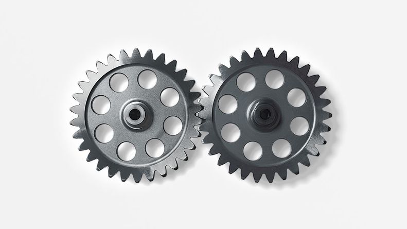
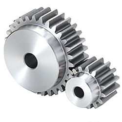
Spur Drive Transmission Planetary Gears
1. Description
| No. | Item | Description |
| 1 | Name | Straight Gear |
| 2 | Size | Products can be customized. |
| 3 | Manufacture Standard | 5-8 Grade ISO1328-1997. |
| 4 | Material | 45#Steel,20CrMnTi,40Cr,20CrNiMo,20MnCr5,GCR15SiMn,42CrMo,2Cr13stainless steel,Nylon,Bakelite,Copper,Aluminium.etc |
| 5 | Production Process | The main process is Gear Hobbing, Gear Shaping and Gear Grinding, Selecting production process according to the different products. |
| 6 | Heat Treatment | Carburizing and quenching ,High-frequency quenching,Nitriding, Hardening and tempering, Selecting heat treatment according to the different materials. |
| 7 | Testing Equipment | Rockwell hardness tester 500RA, Double mesh instrument HD-200B & 3102,Gear measurement center instrument CNC3906T and other High precision detection equipments |
| 8 | Certification | GB/T19001-2016/ISO9001:2015 |
| 9 | Usage | Used in printing machine, cleaning machine, medical equipment, garden machine, construction machine, electric car, valve, forklift, transportation equipment and various gear reducers.etc |
| 10 | Package | According to customer’s request |
2. Photos
Differential Bevel Gear with Straight teeth
1.Description
| No. | Item | Description |
| 1 | Name | Straight Bevel Gear |
| 2 | Size | Products can be customized. |
| 3 | Material | 45#Steel,20CrMnTi,40Cr,20CrNiMo,20MnCr5,GCR15SiMn,42CrMo,2Cr13stainless steel,Nylon,Bakelite,Copper,Aluminium.etc |
| 4 | Production Process | The main process is Gear Milling and Gear Shaping, Selecting production process according to the different products. |
| 5 | Heat Treatment | Carburizing and quenching ,High-frequency quenching,Nitriding, Hardening and tempering, Selecting heat treatment according to the different materials. |
| 6 | Testing Equipment | Rockwell hardness tester 500RA, Double mesh instrument HD-200B & 3102,Gear measurement center instrument CNC3906T and other High precision detection equipments |
| 7 | Certification | GB/T19001-2016/ISO9001:2015 |
| 8 | Usage | Used in printing machine, cleaning machine, medical equipment, garden machine, construction machine, electric car, valve, forklift, transportation equipment and various gear reducers.etc |
| 9 | Package | According to customer’s request |
Order process
a. You seng us drawing or sample.
b. We process scheme and quotation for your products.
c. We make the sample and send it to you after you confirmed our design.
d. You confirm the sample then place an order and pay us 50% deposit.
e. We start producing.
f.When the goods is done, you pay us the balance after you confirmed pictures or tracking numbers.
g.Trade is done, thank you!
| Application: | Electric Cars, Machinery, Agricultural Machinery, Industry |
|---|---|
| Hardness: | Hardened Tooth Surface |
| Gear Position: | External Gear |
| Manufacturing Method: | Gear Hobbing, Gear Shaping and Gear Grinding |
| Toothed Portion Shape: | Involute |
| Material: | 45#Steel,20crmnti,40cr,20CrNiMo,20mncr5,Gcr15simn, |
| Samples: |
US$ 40/Piece
1 Piece(Min.Order) | |
|---|
| Customization: |
Available
| Customized Request |
|---|
How do you calculate the efficiency of a spur gear?
Calculating the efficiency of a spur gear involves considering the power losses that occur during gear operation. Here’s a detailed explanation:
In a gear system, power is transmitted from the driving gear (input) to the driven gear (output). However, due to various factors such as friction, misalignment, and deformation, some power is lost as heat and other forms of energy. The efficiency of a spur gear represents the ratio of the output power to the input power, taking into account these power losses.
Formula for Calculating Gear Efficiency:
The efficiency (η) of a spur gear can be calculated using the following formula:
η = (Output Power / Input Power) × 100%
Where:
η is the efficiency of the gear system expressed as a percentage.
Output Power is the power delivered by the driven gear (output) in the gear system.
Input Power is the power supplied to the driving gear (input) in the gear system.
Factors Affecting Gear Efficiency:
The efficiency of a spur gear is influenced by several factors, including:
- Tooth Profile: The tooth profile of the gear affects the efficiency. Well-designed gear teeth with accurate involute profiles can minimize friction and power losses during meshing.
- Lubrication: Proper lubrication between the gear teeth reduces friction, wear, and heat generation, improving gear efficiency. Insufficient or inadequate lubrication can result in increased power losses and reduced efficiency.
- Gear Material: The selection of gear material affects efficiency. Materials with low friction coefficients and good wear resistance can help minimize power losses. Higher-quality materials and specialized gear coatings can improve efficiency.
- Gear Alignment and Meshing: Proper alignment and precise meshing of the gear teeth are essential for optimal efficiency. Misalignment or incorrect gear meshing can lead to increased friction, noise, and power losses.
- Bearing Friction: The efficiency of a gear system is influenced by the friction in the bearings supporting the gear shafts. High-quality bearings with low friction characteristics can contribute to improved gear efficiency.
- Load Distribution: Uneven load distribution across the gear teeth can result in localized power losses and reduced efficiency. Proper design and gear system configuration should ensure even load distribution.
Interpreting Gear Efficiency:
The calculated gear efficiency indicates the percentage of input power that is effectively transmitted to the output. For example, if a gear system has an efficiency of 90%, it means that 90% of the input power is converted into useful output power, while the remaining 10% is lost as various forms of power dissipation.
It’s important to note that gear efficiency is not constant and can vary with operating conditions, lubrication quality, gear wear, and other factors. The calculated efficiency serves as an estimate and can be influenced by specific system characteristics and design choices.
By considering the factors affecting gear efficiency and implementing proper design, lubrication, and maintenance practices, gear efficiency can be optimized to enhance overall gear system performance and minimize power losses.
What are the advantages and disadvantages of using spur gears?
Spur gears offer several advantages and disadvantages when used in mechanical systems. Here’s a detailed explanation of the advantages and disadvantages of using spur gears:
Advantages of Spur Gears:
- Simplicity: Spur gears have a simple and straightforward design, consisting of cylindrical gears with straight teeth. Their simplicity facilitates ease of manufacturing, installation, and maintenance.
- Efficiency: Spur gears are highly efficient in transmitting power from one shaft to another. They have minimal sliding friction between the gear teeth, resulting in high mechanical efficiency.
- Cost-Effectiveness: Due to their simple design and ease of production, spur gears are generally more cost-effective compared to other types of gears. They are widely available and can be manufactured in large quantities at a reasonable cost.
- Compactness: Spur gears have a compact design, making them suitable for applications where space is limited. They can be arranged in parallel or stacked configurations to achieve the desired gear ratios within a confined space.
- High Load Capacity: Spur gears can handle high load capacities and transmit substantial amounts of torque. Their teeth are designed to distribute the load evenly across the gear face, resulting in improved load-bearing capabilities.
- Precision: Spur gears provide precise and predictable motion due to the simplicity of their tooth engagement. This makes them suitable for applications that require accurate positioning and synchronization.
Disadvantages of Spur Gears:
- Noisy Operation: Spur gears can produce noise during operation, especially at high speeds. The engagement of the gear teeth generates impact and vibration, resulting in noise that may require additional measures to mitigate.
- Axial Thrust: Spur gears generate axial thrust forces along the gear shafts due to the parallel arrangement of their teeth. This thrust must be properly managed using thrust bearings or other means to prevent excessive axial loading on the gear shafts.
- Limited Speed Ratio: Spur gears are primarily designed for applications with moderate speed ratios. They are less suitable for high-speed applications due to the limitations imposed by the tooth engagement and potential for increased noise and vibration.
- Unidirectional Operation: Spur gears are typically designed for unidirectional power transmission. Reversing the direction of rotation can cause noise, impact, and increased wear due to the abrupt change in tooth engagement.
- Prone to Wear: The sliding contact between the gear teeth in spur gears can result in wear over time, especially under heavy loads or inadequate lubrication. Regular maintenance and proper lubrication are necessary to minimize wear and extend gear life.
It’s important to consider these advantages and disadvantages when selecting gear types for specific applications. While spur gears are well-suited for many applications, other gear types, such as helical gears or bevel gears, may be more suitable in certain situations depending on the requirements and operating conditions.
How do you choose the right size spur gear for your application?
Choosing the right size spur gear for your application requires careful consideration of various factors. Here’s a detailed explanation of the steps involved in selecting the appropriate size spur gear:
- Determine the Required Torque: Start by determining the torque requirements of your application. Calculate or estimate the maximum torque that the gear will need to transmit. Consider factors such as the power input, speed, and load conditions to determine the required torque.
- Identify the Speed Requirements: Determine the desired rotational speed or RPM (revolutions per minute) for your application. This will help in selecting a gear with the appropriate pitch diameter and tooth configuration to achieve the desired speed.
- Consider the Load Conditions: Evaluate the expected load conditions, including the magnitude and direction of the load. Determine if the load is constant or variable, and if it involves shock loads or cyclic loading. This will impact the gear’s durability and load-carrying capacity.
- Calculate the Pitch Diameter: Based on the torque and speed requirements, calculate the pitch diameter of the spur gear. The pitch diameter is determined by the formula: Pitch Diameter = (2 x Torque) / (Pressure Angle x Allowable Tooth Shear Stress).
- Select the Module Size: Choose an appropriate module size based on the gear size and application requirements. The module size determines the tooth size and spacing. Smaller module sizes are used for fine tooth profiles and higher precision, while larger module sizes are suitable for heavier loads and higher torque applications.
- Determine the Number of Teeth: Based on the pitch diameter and module size, calculate the number of teeth required for the gear. Ensure that the gear has an adequate number of teeth for smooth operation, load distribution, and sufficient contact ratio.
- Consider Space Constraints: Evaluate the available space and mounting requirements in your application. Ensure that the selected gear size can fit within the available space and can be properly mounted on the shaft or gearbox.
- Choose the Material: Consider the operating conditions, such as temperature, humidity, and presence of corrosive substances, to select the appropriate material for the spur gear. Common materials include steel, cast iron, brass, and plastic. Choose a material that offers the necessary strength, wear resistance, and durability for your specific application.
- Consider Additional Design Features: Depending on your application requirements, you may need to consider additional design features such as profile shift, hub configuration, and surface treatments. Profile shift can optimize gear performance, while specific hub configurations and surface treatments may be necessary for proper mounting and enhanced durability.
It’s important to note that gear selection is a complex process, and it may require consultation with gear manufacturers or experts in the field. They can provide guidance based on their expertise and assist in selecting the most suitable spur gear for your specific application.
By thoroughly considering factors such as torque requirements, speed, load conditions, pitch diameter, module size, number of teeth, space constraints, material selection, and additional design features, you can choose the right size spur gear that meets the demands of your application in terms of performance, durability, and efficiency.


editor by CX 2023-10-24